Reverse engineer USB stack of Exynos BootROM
Posted on Tue 16 June 2020 in Article
In the previous post, we explained how to dump Exynos bootROM.
Exynos (8895 in this post) bootROM contains a minimal USB stack to load a signed bootloader from an USB host (a.k.a. boot from USB). This post summarizes how this USB stack can be reversed using the Great Tool Ghidra and Linux kernel source code.
The goal is to locate and analyze the proprietary USB protocol used to load the bootloader in RAM.

SoC level
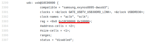
Device Tree Source files in Linux kernel provide a detailed description (like physical address and size) of Exynos SoC peripherals, including the USB controller. In file arch/arm64/boot/dts/exynos/exynos8895.dtsi, we learn that the USB controller is mapped at 0x10C00000 (also known as base address):
Ghidra Memory Map feature allows us to create a memory block that represents this USB peripheral :
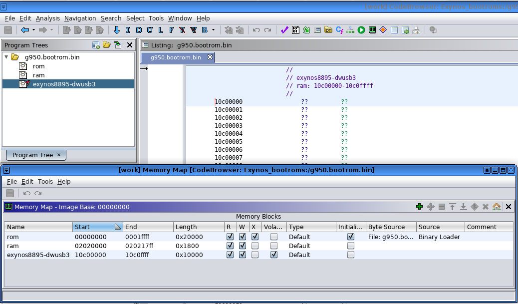
Don't forget to click Analysis>Auto Analyze to update cross references to our new memory block.
Peripheral level
The Linux kernel also contains a list of registers and their offset to interact with the USB controller :
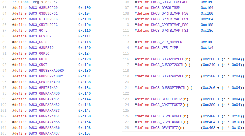
Register offsets are relative to the base address mentioned earlier. Based on this list, we can rename each USB register referenced from the bootROM code (Navigation->Next Data) :
Adding names will help us to understand the purpose of functions that access these registers.
Driver level
BootROM functions that access USB registers directly are dedicated to USB operations. They are similar to the Linux USB driver code, but simplified since bootROM is bare metal code, without interrupt handlers, threads or even dynamic memory allocation.
Despite the lack of public documentation, we can study the Linux USB driver code to understand the purpose of most important USB registers.
With a better understanding of these registers, we can now infer the purpose of bootROM functions based on read/write operations they perform on these registers. In some cases, bootROM and Linux USB driver functions have such similar access patterns (to USB registers) that they can be quickly identified by comparison.
USB enumeration and configurration
Per USB specifications, when a new device is attached, USB host assigns it an unique address by sending the Standard Device Request USB_REQ_SET_ADDRESS. Device must then set its assigned address by writing it to register DWC3_DCFG. And thanks to the Linux USB driver, we even know that device address is a 7-bit value at offset 3 in this register.
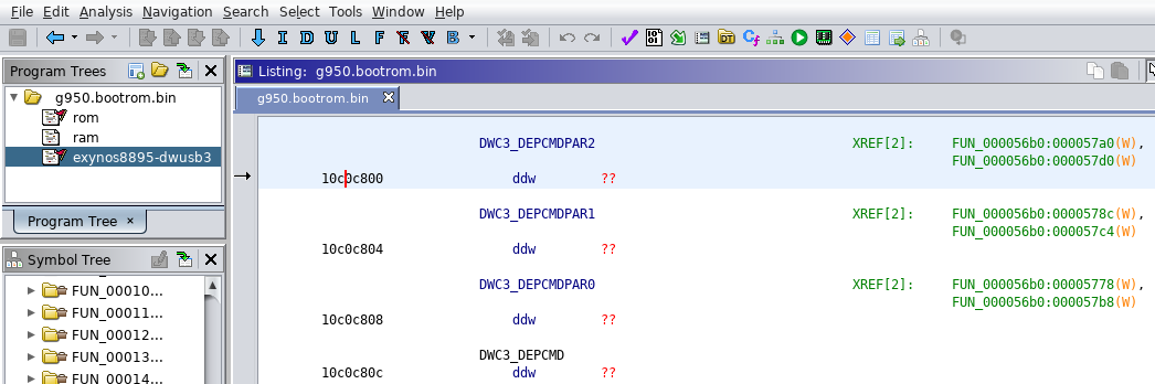
By looking at references to DWC3_DCFG in Ghidra, we can locate bootROM functions that access this register :

Among these functions, only write_DWC3_DCFG_DEVADDR sets device address in DWC3_DCFG register :
void write_DWC3_DCFG_DEVADDR(uint devaddr) {
  uint uVar1;

  uVar1 = cRead_4(DWC3_DCFG);
  cWrite_4(DWC3_DCFG,uVar1 & 0xfffffc00 | uVar1 & 7 | (devaddr & 0x7f) << 3);// DWC3_DCFG[3:7] : device address
  return;
}
By exploring incoming function calls to write_DWC3_DCFG_DEVADDR, we can easily locate the function that handles all incoming Standard Device Requests :
void usb_handle_standard_device_request(longlong param_1,uint *param_2)

{
  //[...]
  bRequest = *(char *)(param_1 + 1);
  if (bRequest == USB_REQ_SET_ADDRESS) {
    write_DWC3_DCFG_DEVADDR((ulonglong)*(byte *)(param_1 + 2));//set device address assigned by USB host
    *(undefined4 *)(puVar3 + 0x30) = 2;
    *param_2 = 0;
    return;
  }
  if (bRequest == USB_REQ_GET_DESCRIPTOR) {
    descriptorType = *(char *)(param_1 + 3);
    if (descriptorType == USB_DT_DEVICE) {
      usb_init_device_descriptor(sUSBBuffers_ptr[1].event_buffer + 0x70);
      if (0x12 < *param_2) {
        *param_2 = 0x12;
      }
    }
    else {
      if (descriptorType == USB_DT_CONFIG) {
        puVar2 = USBBuffers_ptr + 1;
        usb_init_descriptors(puVar2->event_buffer + 0x70);
  //[...]
}
Among all Standard Device Requests sent during USB enumeration phase, USB_REQ_GET_DESCRIPTOR is another interesting one.
USB descriptors are sent to USB host in order to describe device, interface & endpoints implemented by the device. These structures are part of the USB standard, so we can simply import structure definitions (struct USB_DESCRIPTORS & USB_DEVICE_DESCRIPTOR) from Linux kernel in Ghidra (File->Parse C source...) :
void usb_init_device_descriptor(USB_DEVICE_DESCRIPTOR *param_1) {
  param_1->bLength = 0x12;
  param_1->bDescriptorType = 1; // USB_DT_DEVICE
  param_1->bcdUSBL = 0;
  param_1->bcdUSBH = 2;
  param_1->bDeviceClass = 0;
  param_1->bDeviceSubClass = 0;
  param_1->bDeviceProtocol = 0;
  param_1->bMaxPacketSize0 = (byte)DAT_02021544;
  param_1->idVendorL = 0xe8;
  param_1->idVendorH = 4; // VENDOR ID 0x04E8
  param_1->idProductL = 0x34;
  param_1->idProductH = 0x12; //PRODUCT ID 0x1234
  param_1->bcdDeviceL = 0;
  param_1->bcdDeviceH = 1;
  param_1->iManufacturer = 1;
  param_1->iProduct = 2;
  param_1->iSerialNumber = 3;
  param_1->bNumConfigurations = 1;
  return;
}
void usb_init_descriptors(USB_DESCRIPTORS *param_1) {
  byte bVar1;
  byte bVar2;
  undefined4 uVar3;

  uVar3 = DAT_02021548;
  (param_1->oDescConfig).bLength = 9;
  (param_1->oDescConfig).bDescriptorType = 2; // USB_DT_CONFIG
  (param_1->oDescConfig).wTotalLengthL = 0x20;
  (param_1->oDescConfig).wTotalLengthH = 0;
  (param_1->oDescConfig).bNumInterfaces = 1;
  (param_1->oDescConfig).bConfigurationValue = 1;
  (param_1->oDescConfig).iConfiguration = 0;
  (param_1->oDescConfig).bmAttributes = 0x80;
  (param_1->oDescConfig).maxPower = 0xfa;
  (param_1->oDescInterface).bLength = 9;
  (param_1->oDescInterface).bDescriptorType = 4; // USB_DT_INTERFACE
  (param_1->oDescInterface).bInterfaceNumber = 0;
  (param_1->oDescInterface).bAlternateSetting = 0;
  (param_1->oDescInterface).bNumEndpoints = 2;
  (param_1->oDescInterface).bInterfaceClass = 0xff; // USB_CLASS_VENDOR_SPEC
  (param_1->oDescInterface).bInterfaceSubClass = 0;
  (param_1->oDescInterface).bInterfaceProtocol = 0;
  (param_1->oDescInterface).iInterface = 4;
  (param_1->oDescEp0).bLength = 7;
  (param_1->oDescEp0).bDescriptorType = 5; // USB_DT_ENDPOINT
  (param_1->oDescEp0).bEndpointAddress = 0x81; // USB_DIR_IN | 1 : endpoint 1, direction IN
  (param_1->oDescEp0).bmAttributes = 2; // USB_ENDPOINT_XFER_BULK
  bVar1 = (byte)uVar3;
  (param_1->oDescEp0).wMaxPacketSizeL = bVar1;
  bVar2 = (byte)((uint)uVar3 >> 8);
  (param_1->oDescEp0).wMaxPacketSizeH = bVar2;
  (param_1->oDescEp0).bInterval = 0;
  (param_1->oDescEp1).bLength = 7;
  (param_1->oDescEp1).bDescriptorType = 5; // USB_DT_ENDPOINT
  (param_1->oDescEp1).bEndpointAddress = 2; // USB_DIR_OUT | 2 : endpoint 2, direction OUT
  (param_1->oDescEp1).bmAttributes = 2; // USB_ENDPOINT_XFER_BULK
  (param_1->oDescEp1).wMaxPacketSizeL = bVar1;
  (param_1->oDescEp1).wMaxPacketSizeH = bVar2;
  (param_1->oDescEp1).bInterval = 0;
  return;
}
Among the important details in these descriptors, we can learn that this code implements :
- 1 device : vendor ID = 0x04E8, product ID = 0x1234.
- 1 interface of vendor-specific class, which means protocol is likely proprietary.
- 2 bulk endpoints : endpoint 1 for BULK IN transfers, endpoint 2 for BULK OUT transfers.
Event buffer setup
During USB initialization, USB driver allocates a buffer called event buffer and informs USB controller by writing its address and size into registers DWC3_GEVNTADRLO, DWC3_GEVNTADRHI, DWC3_GEVNTSIZ. Once setup, USB controller can write events intended for USB driver into this shared buffer.
In Linux kernel, these registers are accessed by a single function dwc3_event_buffers_setup, called once during USB driver initialization. In bootROM code, event buffer is setup in the same way :
void usb_setup_event_buffer(dword bufferHigh,dword bufferLow,ushort bufferSize) {
  uint local_14;
  uint uVar1;

  cWrite_4(DWC3_GEVNTADRHI,bufferHigh);
  cWrite_4(DWC3_GEVNTADRLO,bufferLow);
  uVar1 = cRead_4(DWC3_GEVNTSIZ);
  local_14 = uVar1 & 0xffff0000 | (uint)bufferSize;
  cWrite_4(DWC3_GEVNTSIZ,local_14);
  return;
}
Events written to this buffer are 32-bit values with different structures depending on their type : either device or endpoint event. These structures, defined in the Linux kernel, can be imported into Ghidra to facilitate the reversing process.
struct dwc3_event_depevt {// Device Endpoint Events
    u32 one_bit:1;// not used
    u32 endpoint_number:5;// number of the endpoint
    u32 endpoint_event:4;// event type
    u32 reserved11_10:2;
    u32 status:4;// Indicates the status of the event
    u32 parameters:16;// Parameters of the current event
} __packed;

struct dwc3_event_devt {// Device Events
    u32 is_devspec:1;// indicates this is a non-endpoint event (device-specific)
    u32 device_event:7;// indicates it's a device event
    u32 type:4;// type of device event
    u32 reserved15_12:4;
    u32 event_info:9;// Information about this event
    u32 reserved31_25:7;
} __packed;
USB events count
Register DWC3_GEVNTCOUNT (updated by USB controller) contains the count of events pending in event buffer. BootROM code implements a simple function (named read_DWC3_GEVNTCOUNT here) to read this register :
uint read_DWC3_GEVNTCOUNT(void) {
  uint eventCnt;

  eventCnt = cRead_4(DWC3_GEVNTCOUNT);
  return (uint)(int)(short)(eventCnt >> 2);
}
Again, we located that function by looking at references to DWC3_GEVNTCOUNT register.
USB event handler
By inspecting incoming function calls in Ghidra, we can now easily locate the main function that processes USB events :
void usb_event_handler(void) {
  dwc3_event evt;
  uint evtCnt;

  evtCnt = read_DWC3_GEVNTCOUNT();//read pending events count from DWC3_GEVNTCOUNT register
  if (evtCnt != 0) {
    while (0 < evtCnt) { // loop while pending events available
      evt = *(USBBuffers_ptr->event_buffer + usbEventIdx * 4); // read event from event buffer
      if (evt != 0) {
        if ((evt & 1) == 0) {// evt.is_devspec == 0 : event is endpoint-specific
          epNum = evt >> 1 & 0x1f;// extract endpoint_number from event
          if (epNum < 2) {// endpoint 0 (bit 0 of endpoint_number is direction: 0=>OUT, 1=>IN)
            usb_handle_ep0_event(&evt);
          }
          else {//other endpoints
            usb_handle_ep_event((ulonglong)(epNum >> 1),(ulonglong)(evt >> 6 & 0xf));
          }
        }
        else {// evt.is_devspec == 1 : event is device-specific
          if ((evt & 0xfe) == 0) {
            usb_handle_device_event(&evt);
          }
        }
      }
      usbEventIdx = usbEventIdx + 1 & 0x1f;
      write_DWC3_GEVNTCOUNT(1);
      evtCnt--;
    }
  }
  return;
}
Instead of relying on interrupts like in Linux driver, this handler implements a polling loop to check for new events in event buffer. Then, events are dispatched to three different functions depending on their type :
- usb_handle_device_event : device-level events like (dis)connect USB cable, reset, link status change,...
- usb_handle_ep0_event : default control endpoint 0 to enumerate & configure device
- usb_handle_ep_event : dispatch events related to other endpoints, including bulk endpoints
The latter usb_handle_ep_event is the one we're interested in, because it handles data received from USB host (i.e. bootloader image). In this function, a dispatch table calls a handler specific to each endpoint number. The only implemented handler in this table is for endpoint 2. Based on configuration descriptors detailed above, we can confirm that endpoint 2 is for BULK OUT (host to device) transfers.
Transfer Request Blocks
Events described in the previous sections are only 32-bit values, they don't contain payload data. Actual data transfers are setup using Transfer Request Blocks (TRB)
A TRB is a structure that directs the USB controller where to write (or read, depending on endpoint direction) data for the next transfer on a specific endpoint. The buffer has to be DMA coherent memory directly accessible by both main CPU and USB controller.
/** struct dwc3_trb - transfer request block (hw format) */
struct dwc3_trb {
    u32     bpl;// buffer pointer (low)
    u32     bph;// buffer pointer (high)
    u32     size;// buffer len
    u32     ctrl;// control bitfield
};
Linux driver function dwc3_ep0_start_trans is a good example of how to initiate a data transfer using a TRB :
static int dwc3_ep0_start_trans(struct dwc3 *dwc, u8 epnum, dma_addr_t buf_dma, u32 len, u32 type)
{
struct dwc3_gadget_ep_cmd_params params;
struct dwc3_trb *trb;
struct dwc3_ep *dep;
dep = dwc->eps[epnum];
trb = dwc->ep0_trb;
trb->bpl = lower_32_bits(buf_dma);
trb->bph = upper_32_bits(buf_dma);
trb->size = len;
trb->ctrl = type;
[...]
memset(¶ms, 0, sizeof(params));
params.param0 = upper_32_bits(dwc->ep0_trb_addr);
params.param1 = lower_32_bits(dwc->ep0_trb_addr);
dwc3_send_gadget_ep_cmd(dwc, dep->number, DWC3_DEPCMD_STARTTRANSFER, ¶ms);
[...]
}
First, trb structure is filled using buffer address and its size provided in function parameters. Then, DWC3_DEPCMD_STARTTRANSFER command is issued to USB controller with TRB pointer and endpoint number as arguments.
Back to bootROM code, identifying where TRBs are set is an important step towards our goal. It can lead us to buffers (corresponding to buf_dma here) used for data transfers. Among them, we're especially interested in those used for endpoint 2 (BULK OUT), because they are read back by the code we're ultimately interested in : vendor-specific protocol handlers.
Again, we rely on hardware register accesses performed by dwc3_send_gadget_ep_cmd to locate bootROM functions that can send command DWC3_DEPCMD_STARTTRANSFER.
Send USB command
In Linux driver, the function to send USB commands dwc3_send_gadget_ep_cmd is the only one to access registers DWC3_DEPCMDPAR0, DWC3_DEPCMDPAR1, DWC3_DEPCMDPAR2, DWC3_DEPCMD. And so it is with bootROM. By comparing both, we can deduce the bootROM function prototype :
int usb_send_command (unsigned char endpointNumber, DWC3_DEPCMD_e command, unsigned int param0, unsigned int param1);
Here's the list of commands defined in Linux driver code :
/* Device Endpoint Command Register */
#define DWC3_DEPCMD_DEPSTARTCFG     (0x09 << 0)
#define DWC3_DEPCMD_ENDTRANSFER     (0x08 << 0)
#define DWC3_DEPCMD_UPDATETRANSFER  (0x07 << 0)
#define DWC3_DEPCMD_STARTTRANSFER   (0x06 << 0)
#define DWC3_DEPCMD_CLEARSTALL      (0x05 << 0)
#define DWC3_DEPCMD_SETSTALL        (0x04 << 0)
#define DWC3_DEPCMD_GETSEQNUMBER    (0x03 << 0)
#define DWC3_DEPCMD_GETEPSTATE      (0x03 << 0)
#define DWC3_DEPCMD_SETTRANSFRESOURCE   (0x02 << 0)
#define DWC3_DEPCMD_SETEPCONFIG     (0x01 << 0)
From there, we can explore all incoming function calls to usb_send_command and use the command argument as hint to ease the reversing.
As explained in previous section, we're especially interested in finding calls with command argument DWC3_DEPCMD_STARTTRANSFER, because they setup the TRB for a specific endpoint. In case of endpoint 2 (BULK OUT), the TRB contains the buffer address where data received from USB host will be written to.
With these last bits, we now have enough information to move on to the next level, our initial goal.
Protocol level
In previous sections, we collected the following information :
- interface configuration : USB interface class bInterfaceClass is vendor-specific (0xff)
- endpoint configuration : endpoint 2 (BULK OUT) is expected to receive data.
- TRB setup for transfer buffer : we know where received data is stored.
- endpoint handlers : we identified the handler function for each endpoint.
The vendor-specific interface class indicates that endpoint handler implements a proprietary protocol. Fortunately, a very simple protocol designed to download a bootloader from USB host.
The bootloader is encapsulated in a small structure dldata_s, and sent through USB bulk transfers of 512 bytes. Maximum data size is 321536 bytes.
struct dldata_s {
    u_int32_t unknown0;
    u_int32_t size;// header(8) + data(n) + footer(2)
    u_int8_t  data[n];
    u_int16_t unknown1;//footer
};
Conclusion
Despite the lack of documentation for the USB controller, we extracted enough technical information from Linux kernel drivers to reverse engineer USB stack implemented in Exynos bootROM. We concluded that this stack implements a single, proprietary interface to download a bootloader from USB host.
As a side note, the bootROM code we analyzed doesn't implement any mitigation technique. Probably because, at such early boot stage, performance is critical, MMU is disabled, and entropy is hard.