Analysis of Nexus 5 Monitor mode
Posted on Thu 25 December 2014 in Article
This article will first describe how to locate the Monitor mode code in Nexus 5 firmware (hammerhead-ktu84p-factory-35ea0277, bootloader-hammerhead-hhz11k : c32f8bec310c659c1296739b00c6a8ac). Then, we will try to understand what it does (its functionalities). Finally, you will have to find bugs by yourself because I didn't find any...so far !
Note: Terms (Non-)Secure world & (Non-)Secure state are used as synonyms. Term Normal world is also used as synonym of Non-Secure world.
I. Quick introduction to ARM Security Extensions
"The Security Extensions define two security states: Secure state
and Non-secure state. All instruction execution takes place either
in Secure state or in Non-secure state.[...] The Security
Extensions also define an additional processor mode, Monitor mode,
that provides a bridge between software running in Non-secure state
and software running in Secure state."
"The Secure Monitor Call exception is implemented only as part of
the Security Extensions. The Secure Monitor Call instruction, SMC ,
requests a Secure Monitor function, causing the processor to enter
Monitor mode."
"When an exception is taken, processor execution is forced to an
address that corresponds to the type of exception. This address is
called the exception vector for that exception. A set of exception
vectors comprises eight consecutive word-aligned memory addresses,
starting at an exception base address. These eight vectors form a
vector table."
--
ARM Architecture Reference Manual ARMv7-A
II. OpenSource TrustZone examples
Trusted Execution Environment (TEE) is the "small" secure kernel
executed in Secure state. The Monitor code
is part of the TEE code.
To get an idea of how the Monitor code works, we can take a look at
two TrustZone examples:
- Cortex-A9 TrustZone example by ARM : a simple example of secure and non-secure code that communicates through Monitor mode.
- OP-TEE by STMicroelectronics : an Open Source TEE 1.0 implementation.
After studying these code samples, we can clearly distinguish two
parts in Monitor code:
Monitor mode initialization: called once, at TEE initialization time.
In this code, we can notice two specific instructions :
- Monitor Vector Base Address Register (MVBAR) setup: MVBAR contains the Monitor vector table address. Both samples use the same instructions to setup MVBAR :
- MCR p15,
0, $RX,c12,c0, 1
where $RX is a pointer to the monitor mode's vector table.
- SP register setup: the Monitor mode stack address is set into SP register. This register is banked, which means this value will be automatically restored next time the processor enters in Monitor mode.
Exception vectors: called when an exception is taken to Monitor mode.
Both samples implement a simple Secure Monitor Call (SMC) handler
that switches between the normal and secure worlds when a SMC call
is made. As SMC handler is an entry point to the Secure state, it
would be interesting to analyze it in Nexus 5 firmware.
III. Extracting Nexus 5 firmware
We know that the Monitor code may be embedded into the TEE image.
In the case of Nexus 5, this image can be extracted from stock
ROM.
Once downloaded, we use a small tool to
unpack bootloader-hammerhead-hhz11k.img file. One of extracted
files is an ELF ARM binary named "tz".
IV. Nexus 5 Monitor mode code
To analyze the Nexus 5 TrustZone binary, we can use
IDA Demo 6.6.
Given that setting up MVBAR is very specific to the monitor mode's
initialization code, we use it to locate the Monitor mode's
initialization code in Nexus 5 TrustZone binary.
Using IDA regex search in code disassembly, we look for the
instruction used to write MVBAR :
MCR[[:space:]]+p15, 0, [^,]+,c12,c0, 1
This search returns only 3 occurrences, and one of them also sets
the SP register. These instructions are expected to be found in
Monitor mode initialization code.
IV.1. Monitor mode initialization function
Here's the disassembly of the Monitor mode initialization code
:
LOAD:FE80DB4C init_monitor
LOAD:FE80DB4C                 MSR             CPSR_c, #0xD6 ; switch to Monitor mode
LOAD:FE80DB50                 LDR             R0, =monitor_vector_table ; load monitor vector table ptr into R0
LOAD:FE80DB54                 MCR             p15, 0, R0,c12,c0, 1 ; write R0 to MVBAR
LOAD:FE80DB58                 BL              sub_FE80DB88 ; initialize Non-Secure world
LOAD:FE80DB5C                 LDR             SP, =0xFE82B700
LOAD:FE80DB60                 MRC             p15, 0, R0,c0,c0, 5 ; write MPIDR value to R0
LOAD:FE80DB64                 AND             R0, R0, #0xFF ; keep Affinity level 0 : current virtual CPU id
LOAD:FE80DB68                 MOV             R1, #0x200
LOAD:FE80DB6C                 MUL             R1, R1, R0 ; compute stack offset for current vCPU
LOAD:FE80DB70                 SUB             SP, SP, R1 ; setup Monitor stack register SP
LOAD:FE80DB74                 MOV             R0, #0b100
LOAD:FE80DB78                 MCR             p15, 0, R0,c1,c1, 0 ; set FIQ flag in SCR register
LOAD:FE80DB7C                 ISB             SY      ; flush the pipeline in the processor
LOAD:FE80DB80                 MSR             CPSR_c, #0xD3 ; switch to Supervisor mode
LOAD:FE80DB84                 BX              LR
LOAD:FE80DB84 ; End of function init_monitor
We will now proceed to a detailed analysis of each step.
IV.1.A Switch to Monitor mode
MSR instruction moves an immediate value (here 0xD6) to a Special register (here CPSR_c).
LOAD:FE80DB4C MSR CPSR_c, #0xD6 ; switch to Monitor mode
The Current Program Status Register (CPSR) holds processor status and control information. CPSR with "_c" suffix enables writing of bits<0:7> of CPSR (ARM Ref. B9.3.11). This bitfield controls the processor mode and exception masks.
We can use a simple IDAPython script to replace the immediate value
0xD6 with symbols documented in
ARM Ref. (B1-1148) :
Thus, the instruction becomes:
LOAD:FE80DB4C MSR CPSR_c, #CPSR_MODE_MON OR CPSR_MASK_FIQ OR CPSR_MASK_IRQ ; switch to Monitor mode
This instruction switches the processor to Monitor mode. It also sets CPSR.F and CPSR.I bits to mask FIQ and IRQ exceptions, meaning they cannot be taken.
IV.1.B Setup MVBAR
The Move to Coprocessor from ARM core register instruction (MCR) passes the value of an ARM core register (here R0) to a coprocessor (here CP15).
LOAD:FE80DB50                 LDR             R0, =monitor_vector_table ; load monitor vector table ptr into R0
LOAD:FE80DB54                 MCR             p15, 0, R0,c12,c0, 1 ; write R0 to MVBAR
CP15 c12 register is present on an ARMv7-A implementation that includes Security Extensions. This instruction writes R0 value to MVBAR. R0 contains a pointer to Monitor vector table. We will describe this table later.
IV.1.C Initialize Non-Secure world
The function sub_FE80DB88 is called to initialize the Non-Secure world context:
LOAD:FE80DB88 sub_FE80DB88
LOAD:FE80DB88                MRC             p15, 0, R1,c1,c0, 0 ; read Secure SCTLR
LOAD:FE80DB8C               MOV             R0, #SCR_NS OR SCR_FW OR SCR_AW ; #0x31
LOAD:FE80DB90                MCR             p15, 0, R0,c1,c1, 0 ; switch to Non-Secure (NS) state
LOAD:FE80DB94                ISB             SY
LOAD:FE80DB98               MCR             p15, 0, R1,c1,c0, 0 ; write Secure SCTLR value to NS SCTLR
LOAD:FE80DB9C               MOV             R0, #0
LOAD:FE80DBA0               MCR             p15, 2, R0,c0,c0, 0 ; clear CSSELR
LOAD:FE80DBA4               MCR             p15, 0, R0,c2,c0, 0 ; clear TTBR0
LOAD:FE80DBA8               MCR             p15, 0, R0,c2,c0, 1 ; clear TTBR1
LOAD:FE80DBAC              MCR             p15, 0, R0,c2,c0, 2 ; clear TTBCR
LOAD:FE80DBB0               MCR             p15, 0, R0,c3,c0, 0 ; clear DACR
LOAD:FE80DBB4               MCR             p15, 0, R0,c5,c0, 0 ; clear DFSR
LOAD:FE80DBB8               MCR             p15, 0, R0,c5,c0, 1 ; clear IFSR
LOAD:FE80DBBC               MCR             p15, 0, R0,c5,c1, 0 ; clear ADFSR
LOAD:FE80DBC0              MCR             p15, 0, R0,c5,c1, 1 ; clear AIFSR
LOAD:FE80DBC4                 MCR             p15, 0, R0,c6,c0, 0 ; clear DFAR
LOAD:FE80DBC8                 MCR             p15, 0, R0,c6,c0, 2 ; clear IFAR
LOAD:FE80DBCC                 MCR             p15, 0, R0,c7,c4, 0 ; clear PAR
LOAD:FE80DBD0                 MCR             p15, 0, R0,c10,c2, 0 ; clear PRRR
LOAD:FE80DBD4                 MCR             p15, 0, R0,c10,c2, 1 ; clear NMRR
LOAD:FE80DBD8                 MCR             p15, 0, R0,c10,c4, 0 ; clear "MMUDMTR" ?
LOAD:FE80DBDC                 MCR             p15, 0, R0,c10,c4, 1 ; clear "MMUDCPR" ?
LOAD:FE80DBE0                 LDR             R1, =dword_FE82B8CC ; load Non-Secure VBAR ptr to R1
LOAD:FE80DBE4                 LDR             R0, [R1]
LOAD:FE80DBE8                 MCR             p15, 0, R0,c12,c0, 0 ; write Non-Secure VBAR
LOAD:FE80DBEC                 MOV             R0, #0
LOAD:FE80DBF0                 STR             R0, [R1] ; clear Non-Secure VBAR ptr
LOAD:FE80DBF4                 MCR             p15, 0, R0,c13,c0, 0 ; clear FCSEIDR
LOAD:FE80DBF8                 MCR             p15, 0, R0,c13,c0, 1 ; clear CONTEXTIDR
LOAD:FE80DBFC                 MCR             p15, 0, R0,c13,c0, 2 ; clear TPIDRURW
LOAD:FE80DC00                 MCR             p15, 0, R0,c13,c0, 3 ; clear TPIDRURO
LOAD:FE80DC04                 MCR             p15, 0, R0,c13,c0, 4 ; clear TPIDRPRW
LOAD:FE80DC08                 MOV             R0, #SCR_FW OR SCR_AW ; #0x30
LOAD:FE80DC0C                 MCR             p15, 0, R0,c1,c1, 0 ; switch back to Secure state
LOAD:FE80DC10                 ISB             SY
LOAD:FE80DC14                 BX              LR
LOAD:FE80DC14 ; End of function sub_FE80DB88
First, the security state is switched to Non-Secure. Then, the coprocessor registers banked in both security states (ARM Ref. Banked system control registers) are initialized to zero. Finally, the security state is switched back to Secure.
IV.1.D Setup SP register
On ARMv7-A, Multiprocessor Affinity Register (MPIDR) holds the
processor identification information. In this register,
bits<0:7> are the affinity level 0 (Aff0). This number
represents the current CPU id. Here, this id is used to compute the
stack address of current CPU, which is then stored into SP
register. The stack size for each CPU is 0x200 bytes.
LOAD:FE80DB5C                 LDR             SP, =0xFE82B700
LOAD:FE80DB60                 MRC             p15, 0, R0,c0,c0, 5 ; write MPIDR value to R0
LOAD:FE80DB64                 AND             R0, R0, #0xFF ; keep Affinity level 0 : current virtual CPU id
LOAD:FE80DB68                 MOV             R1, #0x200
LOAD:FE80DB6C                 MUL             R1, R1, R0 ; compute stack offset for current vCPU
LOAD:FE80DB70                 SUB             SP, SP, R1 ; setup Monitor stack register SP
IV.1.E Route FIQ exceptions to Monitor mode
CP15 c1 register is present on an ARMv7-A implementation that
includes Security Extensions. This instruction sets bit<2>
(0x4) in Secure Configuration Register (SCR), which means FIQ
exceptions are now taken to Monitor mode.
LOAD:FE80DB74                 MOV             R0, #0b100 ; SCR.FIQ
LOAD:FE80DB78                 MCR             p15, 0, R0,c1,c1, 0 ; set FIQ flag in SCR register
LOAD:FE80DB7C                 ISB             SY      ; flush the pipeline in the processor
We can also notice that bit<0> (SCR.NS : Non-Secure) is not set, meaning current execution state is Secure.
IV.1.F Switch back to Supervisor mode
This instruction switches the processor to Supervisor mode, and
sets FIQ & IRQ mask bits.
LOAD:FE80DB80 MSR CPSR_c, #CPSR_MODE_SVC OR CPSR_MASK_FIQ OR CPSR_MASK_IRQ ; switch to Supervisor mode
Monitor mode setup is now complete. Monitor code can then be entered through its exception vector table.
IV.2. Monitor Exception Vector Table
The Monitor exception vector table defines exception vectors to
handle exceptions taken to Monitor Mode.
Its structure is described in
ARM Ref. (B1-1167) :
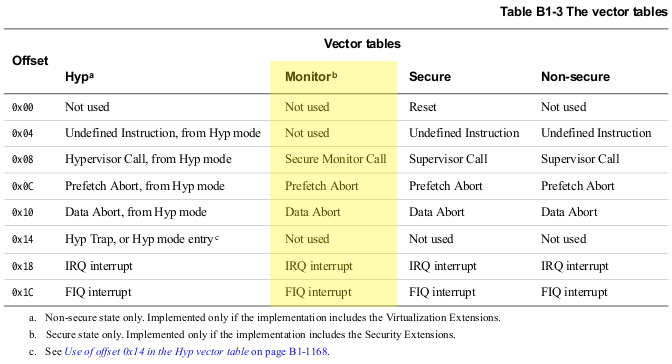
|
| The vector table entries |
Thanks to the Monitor initialization code, we know the address of
Nexus 5's Monitor exception vector table:
LOAD:FE80CEE0 monitor_vector_table
LOAD:FE80CEE0                 B               dead_loop ; not used
LOAD:FE80CEE4 ; ---------------------------------------------------------------------------
LOAD:FE80CEE4                 B               dead_loop ; not used
LOAD:FE80CEE8 ; ---------------------------------------------------------------------------
LOAD:FE80CEE8                 B               smc_handler ; Secure Monitor Call
LOAD:FE80CEEC ; ---------------------------------------------------------------------------
LOAD:FE80CEEC                 B               dead_loop ; Prefetch Abort
LOAD:FE80CEF0 ; ---------------------------------------------------------------------------
LOAD:FE80CEF0                 B               dead_loop ; Data Abort
LOAD:FE80CEF4 ; ---------------------------------------------------------------------------
LOAD:FE80CEF4                 B               dead_loop ; not used
LOAD:FE80CEF8 ; ---------------------------------------------------------------------------
LOAD:FE80CEF8                 B               sub_FE80CF24 ; IRQ interrupt
LOAD:FE80CEFC ; ---------------------------------------------------------------------------
LOAD:FE80CEFC                 B               sub_FE80CFB4 ; FIQ interrupt
LOAD:FE80CEFC ; End of function monitor_vector_table
We can see that 3 exception handlers are configured: SMC, FIQ, IRQ. Others are dead loops.
IV.3. Secure Monitor Call handler function
HLOS (non-Secure state) can call the TrustZone API (Secure state) using the SMC instruction to trigger a Secure Monitor Call exception. This exception is taken to the Monitor mode, which switches the processor to Secure Supervisor mode to proceed the call. When called TrustZone function returns, a second SMC exception is triggered, so the processor enters Monitor mode again. Finally, the Monitor mode returns results to the calling function (Non-Secure state). The Monitor mode acts as a bridge between Non-Secure state and Secure state. It's designed to handle calls initiated from the Non-Secure state only.
The exception vector dedicated to SMC exceptions is a pointer to a
function at offset 0x08 in Monitor Exception Vector Table.
In this function, which will be named SMC handler, the very first
instruction checks if an exception occurred in Secure or Non-Secure
state (When the processor is in Monitor mode, the processor is in
Secure state regardless of the value of the SCR.NS bit).
LOAD:FE80D028 smc_handler
LOAD:FE80D028
LOAD:FE80D028 varg_r0         = -0x10
LOAD:FE80D028 varg_r1         = -0xC
LOAD:FE80D028 varg_r2         = -8
LOAD:FE80D028 varg_r3         = -4
LOAD:FE80D028
LOAD:FE80D028                 STMFD           SP!, {R0-R3}
LOAD:FE80D02C                 MRC             p15, 0, R0,c1,c1, 0 ; read SCR register
LOAD:FE80D030                 TST             R0, #1  ; test SCR.NS bit
LOAD:FE80D034                 BEQ             loc_FE80D210 ; jump if SCR.NS==0
When an exception is taken to the Monitor mode, CPSR.{A,I, F} bits are set to 1, meaning Abort, IRQ and FIQ exceptions can no longer be taken.
IV.3.A. Call to Secure World
If SCR.NS bit is set, it means the Non-Secure world wants to call
the Secure world. We will now analyze the operations performed by
the SMC handler until the exception return to the Secure world.
IV.3.A.a Setup current security state
This first step configures the Secure Configuration Register (SCR). Bits<1:3> (SCR.IRQ || SCR.FIQ || SCR.EA) are set to route IRQ, FIQ, and External Abort exceptions to Monitor mode. But the Non-Secure bit<0> is not set. So, this core will still be in the Secure state if it exits Monitor mode.
LOAD:FE80D038                 MOV             R0, #SCR_IRQ OR SCR_FIQ OR SCR_EA ; 0b1110
LOAD:FE80D03C                 MCR             p15, 0, R0,c1,c1, 0 ; write SCR with SCR.NS==0
LOAD:FE80D040                 ISB             SY      ; Instruction Synchronization Barrier
LOAD:FE80D040                                         ; flushes the pipeline in the processor
IV.3.A.b Monitor calls
On a HLOS like Android, SMC exceptions are triggered by the
Secure Channel Manager (SCM), implemented in Linux kernel.
A quick look at its source code tells us {R0-R3} registers hold
arguments of SMC calls. We also learn that R0 is a bitfield that
can be defined by the following macro:
#define SCM_ATOMIC(svc, cmd, n) (((((svc) << 10)|((cmd) & 0x3ff)) << 12) | \
    SCM_CLASS_REGISTER | \
    SCM_MASK_IRQS | \
    (n & 0xf))
With svc the service identifier, cmd the command identifier, and n
the argument count of the SMC call.
In SMC handler, R0 value is first shifted right by 12. Based on the
SCM_ATOMIC macro definition, resulting R0 value represents a
service identifier svc and a command identifier cmd defined as
((svc) << 10)|((cmd) & 0x3ff).
Then R0 value is tested against several immediate values. For each
case, a specific function is called if values match.
LOAD:FE80D048                 MOV             R2, R0,LSR#12 ; extract service & command identifiers
LOAD:FE80D04C                 MOV             R1, #0x402 ; SCM_SVC_BOOT::SCM_CMD_TERMINATE_PC
LOAD:FE80D050                 CMP             R1, R2
LOAD:FE80D054                 LDMEQFD         SP!, {R1-R3}
LOAD:FE80D058                 BEQ             sub_FE80D360
LOAD:FE80D05C                 MOV             R1, #0xC05 ; SCM_SVC_UTIL::CACHE_BUFFER_DUMP_COMMAND_ID
LOAD:FE80D060                 CMP             R1, R2
LOAD:FE80D064                 LDMEQFD         SP!, {R1-R3}
LOAD:FE80D068                 BEQ             sub_FE80D68C
LOAD:FE80D06C                 MOV             R1, #0x404 ; SCM_SVC_BOOT::4
LOAD:FE80D070                 CMP             R1, R2
LOAD:FE80D074                 LDMEQFD         SP!, {R1-R3}
LOAD:FE80D078                 BEQ             sub_FE80D72C
LOAD:FE80D07C                 MOV             R1, #0x1401 ; SCM_SVC_IO::SCM_IO_READ
LOAD:FE80D080                 CMP             R1, R2
LOAD:FE80D084                 LDMEQFD         SP!, {R1-R3}
LOAD:FE80D088                 BEQ             sub_FE80D5AC
LOAD:FE80D08C                 MOV             R1, #0x1402 ; SCM_SVC_IO::SCM_IO_WRITE
LOAD:FE80D090                 CMP             R1, R2
LOAD:FE80D094                 LDMEQFD         SP!, {R1-R3}
LOAD:FE80D098                 BEQ             sub_FE80D5CC
LOAD:FE80D09C                 MOV             R1, #0x3404 ; SCM_SVC_DCVS::DCVS_CMD_EVENT
LOAD:FE80D0A0                 CMP             R1, R2
LOAD:FE80D0A4                 LDMEQFD         SP!, {R1-R3}
LOAD:FE80D0A8                 BEQ             sub_FE80D64C
LOAD:FE80D0AC                 MOV             R1, #0x1403 ; SCM_SVC_IO::TZ_RESET_ID
LOAD:FE80D0B0                 CMP             R1, R2
LOAD:FE80D0B4                 LDMEQFD         SP!, {R1-R3}
LOAD:FE80D0B8                 BEQ             sub_FE80D5EC
LOAD:FE80D0BC                 MOV             R1, #0x1404 ; SCM_SVC_IO::TZ_UPDATE_ID
LOAD:FE80D0C0                 CMP             R1, R2
LOAD:FE80D0C4                 LDMEQFD         SP!, {R1-R3}
LOAD:FE80D0C8                 BEQ             sub_FE80D618
LOAD:FE80D0CC                 MOV             R1, #0x2401 ; SCM_SVC_PWR::SCM_IO_DISABLE_PMIC_ARBITER
LOAD:FE80D0D0                 CMP             R1, R2
LOAD:FE80D0D4                 LDMEQFD         SP!, {R1-R3}
LOAD:FE80D0D8                 BEQ             sub_FE80D74C
As Linux kernel itself initiates a lot of SMC calls, we explore
Linux sources to enumerate service and command identifiers
passed to SMC calls. Thereby, we will get more information on
corresponding functions without reversing them.
| Immediate value | Service ID (imm>>10) | Command ID (imm&0x3ff) | Function description |
|---|---|---|---|
| 0x402 | SCM_SVC_BOOT | SCM_CMD_TERMINATE_PC | Put current core in low power state |
| 0xC05 | SCM_SVC_UTIL | CACHE_BUFFER_DUMP_COMMAND_ID | Dump the L1 and L2 caches on panic |
| 0x404 | SCM_SVC_BOOT | 4 | Dummy function, returns to Non-Secure world |
| 0x1401 | SCM_SVC_IO | SCM_IO_READ | Dummy function, returns to Non-Secure world |
| 0x1402 | SCM_SVC_IO | SCM_IO_WRITE | Dummy function, returns to Non-Secure world |
| 0x3404 | SCM_SVC_DCVS | DCVS_CMD_EVENT | Handle some Dynamic Clock and Voltage Scaling (DCVS) See also event definitions |
| 0x1403 | SCM_SVC_IO | TZ_RESET_ID | Related to GPU power management |
| 0x1404 | SCM_SVC_IO | TZ_UPDATE_ID | Related to GPU power management |
| 0x2401 | SCM_SVC_PWR | SCM_IO_DISABLE_PMIC_ARBITER | "Force the SPMI PMIC arbiter to shutdown so that no more SPMI transactions are sent from the MSM to the PMIC." |
All these functions have the same epilogue:
LOAD:FE80D738                 MOV             R3, #SCR_NS OR SCR_FIQ OR SCR_AW ; 0b100101
LOAD:FE80D73C                 MCR             p15, 0, R3,c1,c1, 0 ; write SCR : switch to Non-Secure state
LOAD:FE80D740                 ISB             SY
LOAD:FE80D744                 MOV             R3, #0  ; clear R3 to avoid leak
LOAD:FE80D748                 MOVS            PC, LR  ; restore Non-Secure PC & CPSR from LR_mon & SPSR_mon
These instructions switch the processor to Non-Secure state and
restore PC & CPSR to perform an exception return.
So SMC calls associated with these specific command/service IDs are
kind of "Monitor calls", entirely handled in Monitor mode.
But if R0 value does not match these IDs, the execution continues in Monitor mode.
IV.3.A.c TrustZone lock
If the call has not been handled yet, Monitor code tries to acquire a lock to ensure that only one core at a time enters in TrustZone.
First, current CPU id is retrieved from MPIDR. Then, this value is incremented (because 0 means not locked) and used as lock value.
LOAD:FE80D0E0                 LDR             R1, =tz_lock
LOAD:FE80D0E4                 MRC             p15, 0, R2,c0,c0, 5 ; read MPIDR register
LOAD:FE80D0E8                 AND             R2, R2, #0xFF ; extract Aff0 from MPIDR
LOAD:FE80D0EC                 ADD             R2, R2, #1
LOAD:FE80D0F0
LOAD:FE80D0F0 loc_FE80D0F0                            ; CODE XREF: smc_handler+D8j
LOAD:FE80D0F0                 LDREX           R0, [R1] ; read current tz_lock value
LOAD:FE80D0F4                 CMP             R0, #0  ; test if TrustZone is locked
LOAD:FE80D0F8                 STREXEQ         R0, R2, [R1] ; if not locked, try to lock TrustZone
LOAD:FE80D0FC                 CMPEQ           R0, #0  ; test if TrustZone is now locked
LOAD:FE80D100                 BNE             loc_FE80D0F0 ; retry if TrustZone is still not locked
LOAD:FE80D104                 DMB             SY      ; Data Memory Barrier acts as a memory barrier
Then, it tries to acquire the TrustZone lock. This implementation is very similar to the example provided in ARM Ref. (D7.3.1 Acquiring a lock).
It relies on synchronization primitives (LDREX/STREX) to support exclusive accesses to memory shared between cores. Once the lock is acquired, the current core is the only one running in TrustZone, and the execution can continue.
IV.3.A.d Pre-exception status
LR_mon and SPSR_mon are both banked registers. Their values are generated by the exception entry. LR_mon contains the return address in Non-Secure world (right after the SMC instruction). The purpose of SPSR_mon is to record the pre-exception value of the CPSR.
LOAD:FE80D108                 LDR             R0, =NS_core_status ; secure area to store Non-Secure (NS) status
LOAD:FE80D10C                 MOV             R1, LR  ; read NS return address (LR_mon)
LOAD:FE80D110                 MRS             R2, SPSR ; read NS CPSR (SPSR_mon)
LOAD:FE80D114                 STMIA           R0, {R1,R2} ; write LR_mon & SPSR_mon
These two registers are saved in Secure memory to be restored later on exception return.
IV.3.A.e IRQ interruption flag
Then a DWORD at a static address is unconditionally cleared:
LOAD:FE80D118                 LDR             R1, =tz_irq_interrupted
LOAD:FE80D11C                 MOV             R0, #0
LOAD:FE80D120                 STR             R0, [R1] ; clear tz_irq_interrupted value
By looking at cross-references, we notice this DWORD is set to 1 in the IRQ handler of Monitor mode. But in both handlers (SMC & IRQ), when an exception returns to the Non-Secure world, the returned value (in R0) is set to 1 if this DWORD is not null.
Futhermore, we can have a look at how SCM interprets the value returned by a SMC call:
#define SCM_INTERRUPTED  1
do {
    asm volatile(
        __asmeq("%0", "r0")
        __asmeq("%1", "r0")
        __asmeq("%2", "r1")
        __asmeq("%3", "r2")
#ifdef REQUIRES_SEC
        ".arch_extension sec\n"
#endif
        "smc #0 @ switch to secure world\n"
        : "=r" (r0)
        : "r" (r0), "r" (r1), "r" (r2)
        : "r3");
} while (r0 == SCM_INTERRUPTED);
SCM will reiterate each SMC call while the returned value is 1.
We can deduce that this DWORD indicates if the exception return is due to an IRQ interrupt. TrustZone Whitepaper (3.3.3 Secure interrupts) says ARM recommends the use of IRQ as a Normal world interrupt source. That's why IRQ interrupts are handled in the Normal world.
IV.3.A.f Configure Secure world MMU
Next block of instructions modifies the translation table of Secure MMU (ARM Ref. B3.1 About the VMSA) if two conditions are met:
LOAD:FE80D124                 MRC             p15, 0, R0,c0,c0, 5 ; read MPIDR register
LOAD:FE80D128                 AND             R0, R0, #0xFF ; extract Aff0 from MPIDR
LOAD:FE80D12C                 CMP             R0, #0
LOAD:FE80D130                 BNE             loc_FE80D164 ; jump if current core != CPU0
LOAD:FE80D134                 LDR             R0, =tz_ext_elf_loaded ; read external ELF status
LOAD:FE80D138                 LDR             R0, [R0]
LOAD:FE80D13C                 CMP             R0, #0
LOAD:FE80D140                 BEQ             loc_FE80D164 ; jump if no external ELF loaded
LOAD:FE80D144                 LDR             R0, =tz_ext_elf_ttbr0 ; read TTBR0 ptr for external ELF
LOAD:FE80D148                 LDR             R0, [R0]
LOAD:FE80D14C                 DSB             SY
LOAD:FE80D150                 MCR             p15, 0, R0,c2,c0, 0 ; write new TTBR0
LOAD:FE80D154                 ISB             SY
LOAD:FE80D158                 MCR             p15, 0, R0,c8,c7, 0 ; flush TLBs
LOAD:FE80D15C                 DSB             SY
LOAD:FE80D160                 ISB             SY
First, it checks if the current core is CPU0.
Then, it checks if a DWORD is not null. By looking at cross-references, we notice that this DWORD is modified in SCM handler of QSEOS_LOAD_EXTERNAL_ELF_COMMAND call (not part of the Monitor code). This SCM call is made by qseecom_load_external_elf() function in the QSEECOM Linux driver. This function allows the HLOS to load an external ELF binary into the Secure World. We can remark that this function first ensures to run on CPU0.
static int qseecom_load_external_elf(struct qseecom_dev_handle *data, void __user *argp)
{
[...]
 /* SCM_CALL tied to Core0 */
 mask = CPU_MASK_CPU0;
 set_cpu_ret = set_cpus_allowed_ptr(current, &mask);
[...]
You can also refer to TrustZone Whitepaper to learn more about "Secure World processor affinity" on multiprocessor systems.
Finally, if those checks are successful, the Translation Table Base Register 0 (TTBR0) is modified, and data & instruction TLBs are both flushed. TTBR0 holds the physical address of the first-level translation table used by the Secure MMU to perform table translation walks.
This block of instructions will configure the MMU to create a dedicated address space in the Secure World if an external ELF is loaded on CPU0.
IV.3.A.g Context switching
Before switching to Secure World, Normal World context is saved
into Secure memory (TrustZone
Whitepaper, 5.3.1 Context switching). It includes :
- General purpose registers (R0-R12)
- Banked registers SPSR, SP and LR of each mode IRQ, SVC, ABT, UND.
- Banked registers SPSR, R8, R9, R10, R11, R12, SP and LR of FIQ mode.
LOAD:FE80D168                 MOV             LR, SP  ; save Monitor stack address
LOAD:FE80D16C                 LDR             SP, =NS_core_context ; secure area to store Non-Secure context
LOAD:FE80D170                 STMFD           SP, {R0-LR}^
LOAD:FE80D174                 MOV             R4, SP
LOAD:FE80D178                 CPS             #CPSR_MODE_IRQ ; switch to IRQ mode
LOAD:FE80D17C                 MRS             R12, SPSR ; read SPSR_irq
LOAD:FE80D180                 STMIA           R4!, {R12-LR}
LOAD:FE80D184                 CPS             #CPSR_MODE_SVC ; switch to Supervisor mode
LOAD:FE80D188                 MRS             R12, SPSR ; read SPSR_svc
LOAD:FE80D18C                 STMIA           R4!, {R12-LR}
LOAD:FE80D190                 CPS             #CPSR_MODE_ABT ; switch to Abort mode
LOAD:FE80D194                 MRS             R12, SPSR ; read SPSR_abt
LOAD:FE80D198                 STMIA           R4!, {R12-LR}
LOAD:FE80D19C                 CPS             #CPSR_MODE_UND ; switch to Undefined mode
LOAD:FE80D1A0                 MRS             R12, SPSR ; read SPSR_und
LOAD:FE80D1A4                 STMIA           R4!, {R12-LR}
LOAD:FE80D1A8                 CPS             #CPSR_MODE_FIQ ; switch to FIQ mode
LOAD:FE80D1AC                 MRS             R7, SPSR ; read SPSR_fiq
LOAD:FE80D1B0                 STMIA           R4, {R7-LR}
LOAD:FE80D1B4                 CPS             #CPSR_MODE_MON ; switch back to Monitor mode
Because the current security state is Secure (SCR.NS == 0), CPS instructions can be used to switch to each mode before finally switching back to Monitor mode. MRS instruction reads a Special Register (like SPSR) and writes it to a general purpose register.
Later, this saved context will be restored when the processor switches back to the Normal World.
Then, Secure World context is restored from a previous context switch (Secure to Normal World).
LOAD:FE80D1B8                 LDR             SP, =S_core_context ; secure area where previous Secure context is stored
LOAD:FE80D1BC                 MOV             R1, SP
LOAD:FE80D1C0                 CPS             #CPSR_MODE_IRQ ; switch to IRQ mode
LOAD:FE80D1C4                 LDMIA           R1!, {R12-LR}
LOAD:FE80D1C8                 MSR             SPSR_cxsf, R12 ; write SPSR_irq
LOAD:FE80D1CC                 CPS             #CPSR_MODE_SVC ; switch to Supervisor mode
LOAD:FE80D1D0                 LDMIA           R1!, {R12-LR}
LOAD:FE80D1D4                 MSR             SPSR_cxsf, R12 ; write SPSR_svc
LOAD:FE80D1D8                 CPS             #CPSR_MODE_ABT ; switch to Abort mode
LOAD:FE80D1DC                 LDMIA           R1!, {R12-LR}
LOAD:FE80D1E0                 MSR             SPSR_cxsf, R12 ; write SPSR_abt
LOAD:FE80D1E4                 CPS             #CPSR_MODE_UND ; switch to Undefined mode
LOAD:FE80D1E8                 LDMIA           R1!, {R12-LR}
LOAD:FE80D1EC                 MSR             SPSR_cxsf, R12 ; write SPSR_und
LOAD:FE80D1F0                 CPS             #CPSR_MODE_FIQ ; switch to FIQ mode
LOAD:FE80D1F4                 LDMIA           R1, {R7-LR}
LOAD:FE80D1F8                 MSR             SPSR_cxsf, R7 ; write SPSR_fiq
LOAD:FE80D1FC                 CPS             #CPSR_MODE_MON ; switch back to Monitor mode
LOAD:FE80D200                 LDMEA           SP, {R0-LR}^
IV.3.A.f Exception return to Secure world
Finally, the Monitor stack address is restored, and a Return From Exception (RFE) instruction loads the LR and the CPSR of interrupted Secure World from a specific address in Secure memory.
LOAD:FE80D204                 MOV             SP, LR  ; restore Monitor stack address
LOAD:FE80D208                 LDR             LR, =S_core_status ; ptr to previously-saved Secure LR & CPSR
LOAD:FE80D20C                 RFEIA           LR      ; Return From Exception to Secure World
IV.3.B Return to Non-Secure World
In the case where SCR.NS is not set, the Secure world returns results to calling function in Non-Secure world.
A lot of operations here are similar to those previously described in the "Call to Secure World" section.
IV.3.B.a Pre-exception status
First, LR_mon & SPSR_mon registers are saved in Secure memory to be restored next time the TrustZone is entered. LR_mon contains the return address in Secure world (right after the SMC instruction). The purpose of SPSR_mon is to record the pre-exception value of the CPSR.
LOAD:FE80D210                 LDR             R0, =S_core_status ; secure area to store Secure status
LOAD:FE80D214                 MOV             R1, LR  ; read Secure return address (LR_mon)
LOAD:FE80D218                 MRS             R2, SPSR ; read Secure CPSR (SPSR_mon)
LOAD:FE80D21C                 STMIA           R0, {R1,R2} ; write LR_mon & SPSR_mon
IV.3.B.b Context switching
Then, the Secure World context is saved, and the Normal World context is restored from a previous context switch (Normal to Secure World).
LOAD:FE80D224                 MOV             LR, SP  ; save Monitor stack address
LOAD:FE80D228                 LDR             SP, =S_core_context ; secure area to store Secure context
LOAD:FE80D22C                 STMFD           SP, {R0-LR}^
LOAD:FE80D230                 MOV             R4, SP
LOAD:FE80D234                 CPS             #CPSR_MODE_IRQ ; switch to IRQ mode
LOAD:FE80D238                 MRS             R12, SPSR ; read SPSR_irq
LOAD:FE80D23C                 STMIA           R4!, {R12-LR}
LOAD:FE80D240                 CPS             #CPSR_MODE_SVC ; switch to Supervisor mode
LOAD:FE80D244                 MRS             R12, SPSR ; read SPSR_svc
LOAD:FE80D248                 STMIA           R4!, {R12-LR}
LOAD:FE80D24C                 CPS             #CPSR_MODE_ABT ; switch to Abort mode
LOAD:FE80D250                 MRS             R12, SPSR ; read SPSR_abt
LOAD:FE80D254                 STMIA           R4!, {R12-LR}
LOAD:FE80D258                 CPS             #CPSR_MODE_UND ; switch to Undefined mode
LOAD:FE80D25C                 MRS             R12, SPSR ; read SPSR_und
LOAD:FE80D260                 STMIA           R4!, {R12-LR}
LOAD:FE80D264                 CPS             #CPSR_MODE_FIQ ; switch to FIQ mode
LOAD:FE80D268                 MRS             R7, SPSR ; read SPSR_fiq
LOAD:FE80D26C                 STMIA           R4, {R7-LR}
LOAD:FE80D270                 CPS             #CPSR_MODE_MON ; switch back to Monitor mode
LOAD:FE80D274                 SUB             SP, SP, #0x94 ; NS_core_context = SP (S_core_context) - 0x94
LOAD:FE80D278                 MOV             R1, SP  ; secure area where previous Non-Secure context is stored
LOAD:FE80D27C                 CPS             #CPSR_MODE_IRQ ; switch to IRQ mode
LOAD:FE80D280                 LDMIA           R1!, {R12-LR}
LOAD:FE80D284                 MSR             SPSR_cxsf, R12 ; write SPSR_irq
LOAD:FE80D288                 CPS             #CPSR_MODE_SVC ; switch to Supervisor mode
LOAD:FE80D28C                 LDMIA           R1!, {R12-LR}
LOAD:FE80D290                 MSR             SPSR_cxsf, R12 ; write SPSR_svc
LOAD:FE80D294                 CPS             #CPSR_MODE_ABT ; switch to Abort mode
LOAD:FE80D298                 LDMIA           R1!, {R12-LR}
LOAD:FE80D29C                 MSR             SPSR_cxsf, R12 ; write SPSR_abt
LOAD:FE80D2A0                 CPS             #CPSR_MODE_UND ; switch to Undefined mode
LOAD:FE80D2A4                 LDMIA           R1!, {R12-LR}
LOAD:FE80D2A8                 MSR             SPSR_cxsf, R12 ; write SPSR_und
LOAD:FE80D2AC                 CPS             #CPSR_MODE_FIQ ; switch to FIQ mode
LOAD:FE80D2B0                 LDMIA           R1, {R7-LR}
LOAD:FE80D2B4                 MSR             SPSR_cxsf, R7 ; write SPSR_fiq
LOAD:FE80D2B8                 CPS             #CPSR_MODE_MON ; switch back to Monitor mode
LOAD:FE80D2BC                 LDMEA           SP, {R0-LR}^
LOAD:FE80D2C0                 MOV             SP, LR  ; restore Monitor stack address
IV.3.B.c IRQ interrupt flag
Next instructions check the DWORD value which indicates that an IRQ interrupt occurred. If this flag is set, the return value is set to 1 in R0.
LOAD:FE80D2C4                 LDR             R3, =tz_irq_interrupted
LOAD:FE80D2C8                 LDR             R2, [R3]
LOAD:FE80D2CC                 CMP             R2, #0  ; if an IRQ interrupt occurred
LOAD:FE80D2D0                 MOVNE           R0, #1  ; then set return value to 1
This may seem pointless in the context of the SMC handler. But actually this part of code is also used by the IRQ handler to return to the Normal World.
IV.3.B.d Non-secure CPSR & LR
Then CPSR and LR from previously interrupted Non-Secure state are written to SPSR_mon and LR_mon.
LOAD:FE80D2D4                 LDR             LR, =NS_core_status ; ptr to previously-saved Non-Secure LR
LOAD:FE80D2D8                 LDR             LR, [LR] ; restore Non-Secure return address
LOAD:FE80D2DC                 LDR             R3, =NS_core_status.SPSR ; ptr to previously-saved Non-Secure CPSR
LOAD:FE80D2E0                 LDR             R3, [R3]
LOAD:FE80D2E4                 BIC             R3, R3, #CPSR_MASK_FIQ ; clear CPSR.F: FIQ exceptions not masked
LOAD:FE80D2E8                 MSR             SPSR_cxsf, R3 ; write SPSR
LOAD:FE80D2EC                 DMB             SY
They will be used later for the exception return.
IV.3.B.e TrustZone lock
After that, tz_lock DWORD is cleared to indicate that this core is no longer running in TrustZone.
LOAD:FE80D2F0                 LDR             R3, =tz_lock
LOAD:FE80D2F4                 MOV             R2, #0
LOAD:FE80D2F8                 STR             R2, [R3] ; clear tz_lock
LOAD:FE80D2FC                 DMB             SY
IV.3.B.f Exception return to Non-Secure world
The MCR instruction writes to the SCR register to modify the configuration of the current security state:
LOAD:FE80D300                 MOV             R2, #0  ; clear R2 to avoid leak
LOAD:FE80D304                 MOV             R3, #0
LOAD:FE80D308                 MOV             R3, #SCR_NS OR SCR_FIQ OR SCR_AW ; 0b100101
LOAD:FE80D30C                 MCR             p15, 0, R3,c1,c1, 0 ; write SCR : switch to Non-Secure state
LOAD:FE80D310                 ISB             SY
LOAD:FE80D314                 MOV             R3, #0  ; clear R3 to avoid leak
LOAD:FE80D318                 MOVS            PC, LR  ; restore Non-Secure PC & CPSR
LOAD:FE80D318 ; End of function smc_handler
The Security state is switched to Non-Secure (SCR_NS). FIQ interrupts are taken to the Monitor Mode (SCR_FIQ), and the CPSR.A bit can be modified in any security state (SCR_AW), so the Non-Secure world can mask Abort exceptions.
Finally, the exception return is made with a MOVS instruction which branches to the return address in Normal World, and also copies SPSR_mon to CPSR.
Conclusion
We have analyzed a part of Monitor code which allows to switch processor security state through SMC exceptions. We've learnt that some SMC exceptions are fully handled by Monitor code, while others are routed to TrustZone code in Secure Supervisor mode. The latter can be executed by only one core at a time. We have also found that an external ELF can be loaded and executed in TrustZone with a dedicated Secure memory space. However, this analysis is not complete since IRQ & FIQ handlers have not been studied.
--I would like to thank Adrien & Diane for their help!